TEHRI DAM
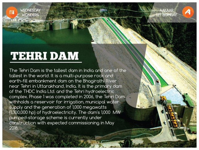
The Tehri Dam is the tallest dam in India, 2nd highest in Asia and 8th tallest in the world. It is a multi-purpose rock and earth-fill embankment dam on the Bhagirathi river near Tehri in Uttarakhand, India. It is the primary dam of the THDC India Ltd. and the Tehri hydro-electric complex. Phase 1 was completed in 2006, the Tehri Dam withholds a reservoir for irrigation, municipal water supply and the generation of 1,000 megawatts (1,300,000 hp) of hydroelectricity. The dam’s 1,000 MW pumped storage scheme is currently under construction with expected commissioning in May 2018.
This mega project of 2000 MW installed capacity, envisaged construction in two stages. The stage‐I, is termed as Hydropower Plant (HPP) and Stage‐II comprising a Pump Storage Plant (PSP), have an installed capacity of 1000 MW each. From inception to the year 1988, the project was executed by Irrigation Department of Uttar Pradesh and afterwards by Tehri Hydro Development Corpn. Ltd. (THDC).
The Tehri Dam withholds a reservoir for irrigation, municipal water supply and the generation of 1,000 megawatts of hydroelectricity.
Construction of Tehri Dam
-
Rocks and External materials used – Consequences
- The Tehri dam rocks are 65% clayey and are thus highly fractured and ridden by earthquake fault lines. Such fault lines could be reactivated by the sheer load of the water.
- The swelling of the soil layer can impose a pressure on the rock layers and tend to crack them. Moreover, when the wet soil layers dry they shrink.
- The Tehri dam is built 1.5 km downstream of the confluence of Bhagirathi and the Bhilangana river. The rocks around the river gorge are mainly of the Chandpur phyllite kind.
- The rocks here have undergone various magnitudes of tectonic deformation.
-
Filling the Earth-Rockfill Tehri Dam
- A major input that is required before a dam is built is the permeability (hydraulic conductivity) of rock masses. When there is a wide variation in the permeability dependence on an average value simply will not suffice especially if one knows that collapse takes place at the weakest link.
- The discontinuity apertures in the rocks are the most important factor for the rock’s hydraulic conductivity. The changes in apertures due to stress could have marked effect on the hydraulic conductivity so that one requires in situ tests such as, what is called, Lugeon tests.
- One of the main drawbacks of the Lugeon test is that each test it is limited to an area of only ~ 100 m2 and a height of ~ 10m. In short, site could not be expected to give reliable engineering information.
- The length across the valley at the crest is ~ 575 m while the base width in the upstream-downstream direction is ~ 1000 m at the base and nearly 20 m at the crest. The design requires an impervious core made up of clayey materials and a shell of graded gravel that is topped with blasted rock which should be massive and mostly quartz.
- The fragile nature of the rockfill as compared to the requirement of rocks surface size between 25 mm to 600 mm size or between 1” and 2 ft size.
- The rocks used for rockfills were obtained from Old Dobata area that lies approximately 5 km upstream of dam site on the right bank of Bhagirathi and new Dobata borrows in Tehri Garhwal district.
- The main difference between the New Dobata borrow and the Old Dobata borrow is that the former had nearly 99% quartz and were white in color while that from the Old Dobata borrow had 96% quartz with more garnet and mica. This suggests that the rocks from the old Dobata borrow were more clayish. The old Dobata borrow rocks should not have been used for the top cover.
-
Choice of dam site
- Because of the very nature of the requirements for tall dams on main rivers, geological boundaries such as thrust lines or major faults are not uncommon, since they provide the necessary geomorphologic features. Major fault lines are known to exist at the Tehri dam site.
- Most important requirement these is that the rocks adjacent to the dam or on the sides of the river should be stable to sliding when wet. The slopes of the banks of the river are dominated by Debris or remains of broken rock because of high levels of fracture, and faulting (of the earthquake kind) and sedimentation.
- As discussed above hydro geological reasons such as low grade phyllitic rocks in the abutments and rim slopes with increased soil moisture due to soaking by the increased height of the reservoir could lead to a sliding of bedrocks and cause large landslides. These landslides would increase the sedimentation rate and drastically reduce the dam’s life for power generation or irrigation.
- Because of the high levels of fracture and sandy character the slopes of the hills are expected to be close to the critical angle of 35 degree. The lower regions of the surrounding hills have a slope considerably larger than 35 degree , however.One may therefore expect these slopes to slide and slip, especially if they soaked and wet as when the reservoir is full. If the entire slope was to attain this critical angle , the level of the bottom of the river would rise roughly to 650-660 ft. Flood waters from higher ranges would fill the river up further.
With a view to provide maximum assurance of safety, the dam has been designed adopting most stringent design criteria, incorporating certain features which would ensure its safety, in an unforeseen major seismic event.
(i) A very conservative design slope, with U/S slope of 2.5:1 and D/S slope of 2.0:1, as against relatively steeper slopes in some recent dams built/proposed in region of very high seismicity.
(ii) A very wide crest of 20m, which increases to 25m at its contact with abutments, has been provided.
(iii) A very liberal free board of 9.5m above FRL has been provided to take care of any settlement, slumping due to earthquake and wave action.
(iv) The D/S filter as designed is capable of preventing migration of finest particles (clay flocks) in the event of its cracking and would not permit any piping. A zone of fine (sand) filter has been provided on the U/S face, which in the unlikely event of cracking of core would get washed into cracks and seal them.
(v) The dam shell material is being compacted to unprecedented high density of minimum 2.36 tons/m3 to ensure little settlement, so that no pore pressure is built up during earthquakes.
(vi) The dam embankment is founded directly on bedrock, after removal of all loose, semi‐ compact overburden, thus eliminating possibility of foundation liquifaction during slaking in the event of any earthquake.
(vii) The provision of access galleries at three different levels, on abutments, below dam seat and within the core to enable physical monitoring during operation, would help taking timely measures, through these galleries, in the event of any distress.
Environmental issues
The Tehri Dam has been the object of protests by environmental organizations and local people of the region. In addition to the human rights concerns, the project has spurred concerns about the environmental consequences of locating such a large dam in the fragile ecosystem of the Himalayan foothills. There are further concerns regarding the dam’s geological stability. The Tehri dam is located in the Central Himalayan Seismic Gap, a major geologic fault zone. This region was the site of a 6.8 magnitude earthquake in October 1991, with an epicenter 53 kilometres (33 mi) from the location of the dam. Dam proponents claim that the complex is designed to withstand an earthquake of 8.4 magnitude, but some seismologists say that earthquakes with a magnitude of 8.5 or more could occur in this region. Were such a catastrophe to occur, the potentially resulting dam-break would submerge numerous towns downstream, whose populations total near half a million.
Tehri Hydro Power Complex (2400 MW), comprises the following components:
- Tehri Dam & Hydro Power Plant (1000 MW)
- Koteshwar Hydro Electric Project (400 MW)
- Tehri Pumped Storage Plant (PSP) (1000 MW)
The dam creates a reservoir of 2.6 cubic kilometres (2,100,000 acre•ft) with a surface area of 52 square kilometres (20 sq mt).
Tehri Dam Advantages
- 2400 megawatt electricity.
- Clean Drinking water to almost 40 lakhs of people living in Delhi.
- Clean Drinking water to almost 30 lakhs of people living in and around Uttar Pradesh.
- Less flooding in low lying areas of Uttar Pradesh , West Bengal and Bihar.
- Employment Generation for the local people.
- 12% of the total electricity generated as royalty to Uttarakhand.
- Increase in Tourism sector , Fish Irrigation Projects and other Govt. Projects in Uttarakhand.
- Rs2400 crores profit to the Central Government every year.
- Land Irrigation water to almost 270,000 hectares to Uttarakhand , Uttar Pradesh and New Delhi.
Tehri Dam Issues
The Tehri Dam project has brought concerns about the environmental problems of locating a large dam in the delicate ecosystem of the Himalayan foothills.
There are growing concerns regarding the dam’s stability. Tehri dam is located 7.5kms above the Central Himalayan Seismic Gap, which is a major geologic fault zone. This region was the site of a 6.8 magnitude earthquake in October 1991, with an epicentre 5 km from the location of the dam. Building of the dam will put further pressure on the seismic gap and thus increases the chances of an earthquake.
The Tehri dam is designed to withstand an earthquake of 8.4 magnitude, but some seismologists say that earthquakes with a magnitude of 8.5 or more could occur in this region.
This could result in a dam-break and the flood waters from the dam could submerge numerous towns comming in the way. Tehri dam has been in active protest by environmental organizations and local people of the region.
With a view to provide maximum assurance of safety, the dam has been designed adopting most stringent design criteria, incorporating certain features which would ensure its safety, in an unforeseen major seismic event.
Conclusion:
Tehri Dam Project, a prestigious hydropower cum irrigation project, is the first major attempt to harness vast hydro potential of Bhagirathi river which is fed by Gangotri Glacier. The storage project in the Bhagirathi valley in Uttarakhand Himalaya, envisages impounding of surplus monsoon water of the river for utilizing it in regulated manner for hydropower generation and irrigation
Sources
- https://lookaside.fbsbx.com/file/A_CASE_STUDY_ON_TEHRI_DAM.pdf?token=AWwDmhUqsrA67lV1PsBVF86krLf40Ey7MIBUighHLfGCrq2yEnn1uvTwqMEWS5hSqMXm5OjqrVIqvIjXFfal-OzV9_SFFInu_uF5mxaLFp3RoiJIUL-fktavFxqnTcVY2XUZe4DZmedspcCguJSl-CIk
- http://www.slideshare.net/bobbysir/tehri-dam-its-implications
- http://www.windiaw.com/tehri-dam-uttarakhand-india/
- https://en.wikipedia.org/wiki/Tehri_Dam
